
11 Jul Stiffness test
Stiffness tests are performed in order to determine the stiffness distribution in different cross-sections along the blade.
Stiffness tests can be performed in both edgewise and flapwise direction. Furthermore a torsional stiffness test can be performed. The reported data enables costumers to calibrate the computer model of a blade. Design engineers in the process of enhancing structural design concepts also use the test results.
After receipt of the blade, a typical blade test includes: determination of blade length, mass, own weight moment and centre of gravity.

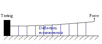
Figure 1 Possible force introduction at the edgewise and flapwise stiffness test.
Figure 2 Possible force introduction at the torsional stiffness test. The blade is being”locked” at the neutral axes.
Edgewise and flapwise stiffness tests:
The blade is bolted to the test rig and a force is applied at a given distance from the root at the neutral axis. Distance transducers measure the deflections at a number of positions along the blade neutral axes. All measured values are stored in the data acquisition system. From the measured deflection curve and the bending moment curve the stiffness distribution can be determined.
Torsional stiffness test:
The blade is bolted to the test rig and a force couple is applied at a given distance from the root in order to get an appropriate torsional bending moment. Distance transducers measure the deflections at the leading and trailing edges at a number of positions along the blade. All measured values are stored in the data acquisition system. From the measured deflections the angular deflection at the different cross-sections along the blade can be determined. With the determined angular deflections and the torsional bending moment a torsional stiffness distribution can be determined.